Currently, many FDM technology-based 3d printer companies send their printers with pre-calibration. But they still require some calibration before the first print. Although if we design a custom-made 3d printer we could do both calibrations at once and save our time. Here we will discuss each aspect of calibrating related and required for 3d printer.
In a well-calibrated printer, your printer hardware’s rhythm with software is iThereoes exactly what it is told to do. You first create a digital model in slicer software that makes the G-code of your design according to it, so you have to configure that your printer is the same as the digital model in the slicer.
Precaution While Making Custom Frame
Many makers around the world are now creating custom build printers because of open-source hardware design and software.
So if you are also creating a custom frame then always use an error-free measurement tool, even a millimeter’s error can cause problems.
While drilling the hole for connection does not make any hurry, take your time and drill them with the correct measurement and alignment.
Calibration For FDM 3D Printers
For FDM 3d printer, you need to calibrate the extruder before any calibration because the extruder is the only piece in your printer that shows you your calibration output.
Calibration Of Extruder
Uncalibrated extruders cause problems like over extrusion or under extrusion so you need to calibrate the extruder necessarily.
To calibrate, the extruder follow these steps:-
- First feed the filament extruder till it come out form the hotend.
- Now measure the 100mm length of filament from extruder and mark it.
- Preheat the hotend.
- Then use extrude command to extrude the 100mm of filament.
- If the mark point does not lie approximately near the extruder borrder it means it have some calibration problem.
- If the mark cross the extruder border then it has over extrution calibration problem or if the mark does not cross the extruder border it has under extrution calibration problem.
- For under extrution problem you need to increase the steps/mm or if you has over extrution problem than decrease the steps/mm.
For correct steps/mm you can use this formula.
Correct steps/mm = Extruded value define by you *[(original steps/mm) / (distance between mark point and extruder border)]
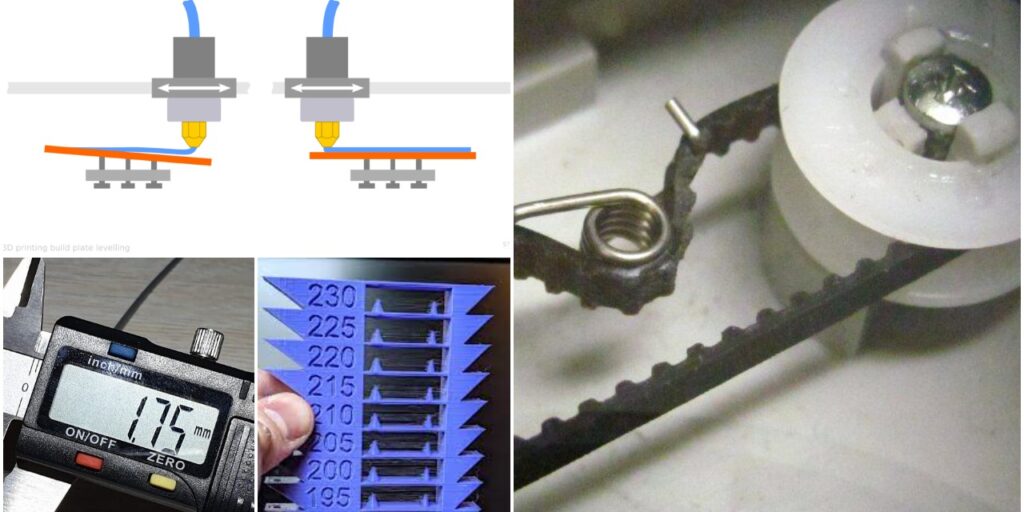
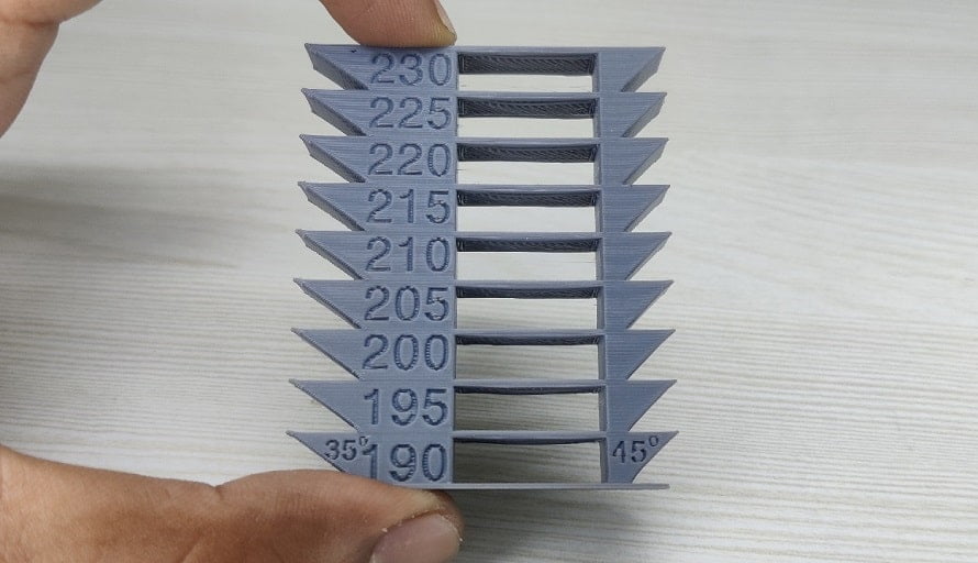
Calibrate The Hotend Temprature
You need to download the temperature tower file below. After that import the model in Cura slicer and follow the below steps:-
- Choose the Material Type.
- Set Layer height between 0.2 to 0.4
- Does not use infill because tower is hollow also does not use top and bottom layer.
- Use a brim to support the tower as 2 support layer.
- Now set different temprature gradiant on different height of tower.
- Go in Extention -> post processing -> Modify gcode
- A window Post Procesing Plugin will open
- Click on Add Scripts
- In trigger option set Layer height.
- Change layer fill with on which layer you want to activate the script
- In Behavoir set Keep Value
- In No. 1 Layer set 1
- Mark the change extruder 1 temprature.
- Enter the increased Value of temprature in Extruder 1 Temp.
- Now click again on Add a scripts button to add another temprature gradiant.
- After add servals scripts slice your model and 3d print it.
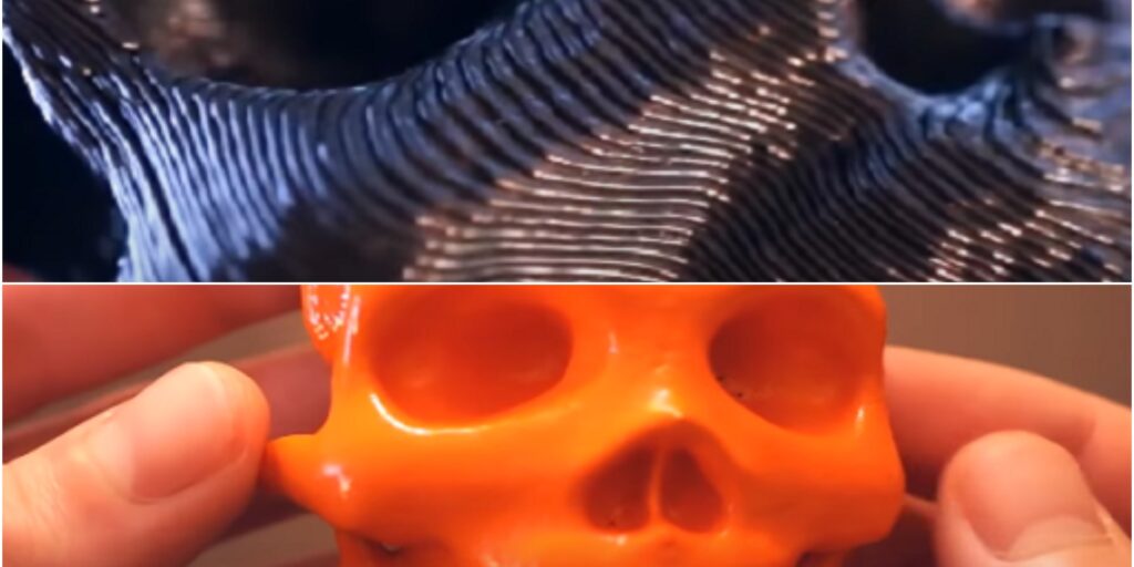
- After print analyze your print for best Layer addesion and surface quality.
- On which layer you find sweet spot for your Printer save that temprature in settings for the Material that you use in calibration.
Note:- After calibration is complete you need to remove these scripts from the Cura slicer otherwise they activate in each print.
Calibrate Tension of Timing Belt
In the real world, there is no 100% assured method to tell you that your timing belt has correct tension but there are some tests from which you can determine it has the best tension.

- The best method is to use a spring which keep the equal linear force on timimg belt.
- Check all the assembly is rigid.
- Pully are fitted well in the bolt.
- Tooth of timming belt is not slipping from pulley.
- No any other object between belt and drive way of belt.
- Timming belt does not have any crack.
- You can also use some mobile application to check the tension of timing belt through vibration of timing belt.
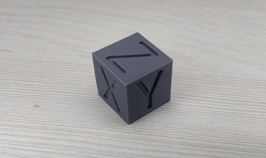
Calibrating X, Y, Z Axis
To calibrate the x, y, z-axis we need to print the calibration cube. you can find the calibration cube on the link given below. After downloading the model of the cube follows these steps.
- Import the cube in slicer software.
- Scale it size as you want.(20mm is default in most cases)
- Slice it according your printer.
- Save .gcode file in sd card and print it.
- After print complete measure the each axis of cube, if the any axis is not equal to 20mm then use the below formula to caluculate the correct steps/mm of that axises.
Correct steps/mm = Current steps/mm * (Expected Length/Printed Length)
Change the steps/mm value of 3d printer for each axis.
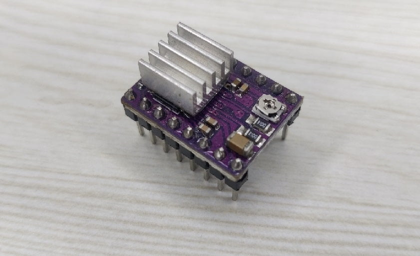
Calibrate Stepper Motor Driver
When you purchase a stepper motor driver they come with default calibration so if you plug them directly without calibrating them your motor becomes hot or did not move due to high and low current.
To calibrate the driver, you need the following things
- Arduino Mega and Ramps.
- Power Supply.
- Stepper Drivers.
- Stepper Motor which is driven by these drivers.
- USB cable for Arduino Mega.
- Mulitimeter or any other current measurable device.
After getting all the above-mentioned items to follow these steps to calibrate your stepper motor driver-
- Connect Arduino mega with ramps and insert driver in x-axis also upload the 3d printer firmware.
- Connect multimeter with ramps power connecter and power supply in series.
- Set the multimeter on DC current.
- Turn on the power supply.
- Connect the USB cable to the PC and open the Repeteter Host.
- Connect the stepper motor to the x-axis driver motor pin.
- Check current reading now send command from software to move the x-axis.
- While the stepper motor is moving check the current rating from the multimeter and subtract the initial current reading from it if the current reading is HIGH or LOW then necessary limits.
- Adjust the potentiometer of the driver to get the preferred current rating.
- After calibration is done remove the driver and insert another Motor driver.
Note:- If you use two motors in parallel then double the preferred current.
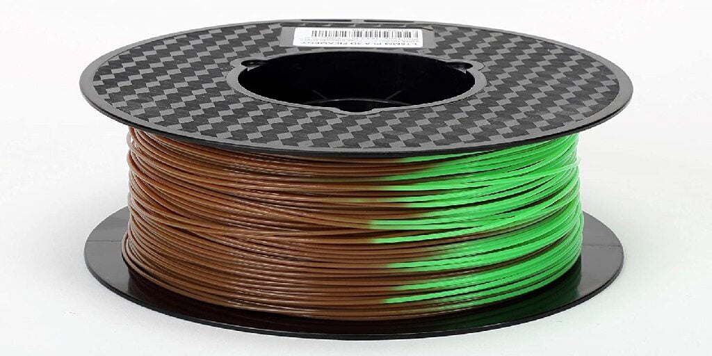
Calibrate the Filament Size

In Filament calibration, you need to do just measure the filament diameter on a random length of filament after that take average of these values and feed the average in machine
Calibrate the build Plate
In the FDM printer Build Plate calibration is also known as bed leveling. Now it can be done via the printer self with the help of the calibration sensor. There are many different types of automatic bed leveling sensors available in the market so you can choose any of them but check the datasheet that the sensor supports your build plate type. Calibration sensor easy the work but if you do not use the sensor to calibrate the build plate then follow the following steps to calibrate it.

- First check nozzle is clean if not then heatup the hot end and clean the nozzle.
- After cleaning the nozzle, cool down the each heater cartridge.
- Send command to printer to lower the z-axis.
- Take A4 paper or any other thin sheet of any material and put between the nozzle and build plate now addjust the build plate untill you feel little friction while moving the sheet between the nozzle and the build plate, at that point you do same procejure for all others corners of 3d printer. After that you build plate calibration is complete.
Conclusion
We have discussed many different types of calibration for FDM 3d Printers but there are many more types of calibration that are done while assembling the printer or into the software of the Printer, some of them are.
- PID Tuning
- Retraction Calibration
- Acceleration and Jerks calibration etc.
These are not that common and are required rarely so we have not discussed them in this post.
Calibration minimizes the vibration of the printer so with a well-calibrated 3d printer you can achieve good surface quality at a higher speed.
For a different design, the calibration process is the same for most of the components.
Some 3d printers also calibrate themselves in a single click but they are expensive due to the use of complex software and hardware.
After that you can test your printer calibration by print some complex models on the printer this gives you an idea of how good your printer is calibrated.
In case you have any doubt please ask in the comment box. Thank You.