This Arduino Claw Arm robot was built to take learning to the next level. This advanced educational robot provides an all-in-one solution for STEAM–based classrooms everywhere, offering AI and programming projects for students of all ages and experience levels. This wireless Arduino car is an unrivaled educational tool with powerful mechanical accessories and unlimited expandability options. It is made of steel and finished with a sleek, futuristic design, with cutting-edge technologies that provide consistent support.
This article will be on how the consistent supports of an arm and a servo claw are provided to a Mecanum wheel robot? The Robot has been inspired by DJI Robomaster Ep Core and it is used for various applications. The Mecanum wheel is an omnidirectional wheel design for a land-based vehicle to move in any direction. The chassis (For details: Click Here) provides mechanical support to the robot for heavy loads. A robot arm has a mechanical structure that alters its form using a group of electric motors that behave like servo motors, pneumatic, or hydraulic actuators. They attempt to reproduce movement similar to a human arm.
You must consider several factors when constructing a robot arm, including the maximum load weight, the stall torques of each one of the servos, how much weight each servo must support related to its position in the arm, and the weight of each part that constitutes the arm frame.
Let’s dive into the details of it.
Arduino Car & Claw STL Files
The .STL files are basically finished CAD models used for detailed engineering of 3D models or 2D drawings of physical components. It takes about 15-17 hours(roughly) to print the arm and claw at 20% infill, with a 0.2mm layer height. It should be noted, that none of the parts of the claw or the arm require support while 3D printing.
You can download the files from the links given below.
You may as well, read the information about the files by reading it from the product page. Once downloaded, you can see all the printable files required to make the robot.
Claw Arm Arduino Robot Assembly
We have already talked about the assembly o the Car body in our previous blog, you can check it by clicking DIY Mecanum Wheel Robot Car.
The body of a Mecanum Wheel Robot has to be assembled, to attach the servo claw and the arm to it. Therefore, first remove the front, back body, and the battery of the car. Now, comes the next part i.e. assembling the Arm.
Components Required For The Claw Arm
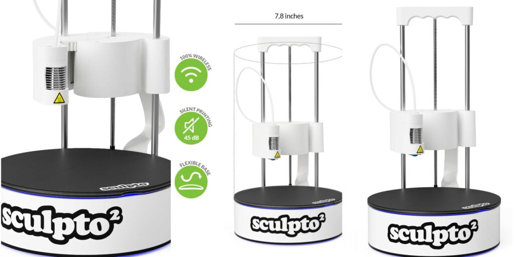
Internet sites offer thousands of robot arm kits, instructions for building your own robot out of wood, metal, scrap materials, and more. But, here we have used the most simple method i.e. PLA which is easily printable on your homemade 3D Printer of volume 220x220x220(mm). If you don’t have one and want to build it for under $200 then you can check out the post below.
Homemade 3D Printer | Simple DIY Under $150
The assembly procedure of the arm takes around two hours when done without error. The kit has many screws divided into M3 8mm, M3 8mm flathead screws, M3 10mm, and M3 15mm and it is very important to understand where each screw goes to guarantee the smooth functioning of your arms body.
The Components Required For The Claw Arm
| Component | Quantity | Link (Affiliate) |
|---|---|---|
| M3 Allen Nuts and Bolts | As Required | IND – M3 Allen Nuts & Bolts (Amazon.in) USA – M3 Allen Nuts & Bolts (Amazon.com) Aliexpress – M3 Allen Nuts & Screws (Aliexpress.com) |
| 12 Volt Male Female Jack | As Required | IND – Male Female Jack (Amazon.in) USA – Male Female Jack (Amazon.com) |
| SG 90 Servo | 1 | IND – SG 90 Servo (Amazon.in) USA – SG 90 Servo (Amazon.com) Aliexpress – SG 90 Servo (Aliexpress.com) |
| MG 90S Servo (In place of SG 90 for Better Strength) | 1 | IND – MG 90S Servo (Amazon.in) USA – MG 90S Servo (Amazon.com) Aliexpress – MG 90S Servo (Aliexpress.com) |
| MG995 Servo | 2 | IND – MG995 Servo (Amazon.in) USA – MG995 Servo (Amazon.com) Aliexpress – MG995 Servo (Aliexpress.com) |
| Screw Driver Kit | Set | IND – Screw Driver Kit (Amazon.in) USA – Screw Driver Kit (Amazon.com) Aliexpress – Screw Driver Kit (Aliexpress.com) |
The usage of the screws is summarized as follows:
- The M3 10mm screws are used in the bearings to connect the servo that will manipulate the gripper and the wrist.
- The M4 10mm screws connect the servos with servo brackets.
- The M3 8mm fat screws connect the servo wheel to the servo only.
- The M3 9mm rounded screws connect the rest of the arm parts –like the short U-shapes –to each other and the servo to the long U-shapes.
The configuration is enough to keep your servos running smoothly.
Assembling The Claw
The claw contains very simple movement –it opens and closes-so only one servo is necessary. It is made from various small parts which have been 3D printed in black and grey. You can choose the color of the filaments according to your design. The 3D parts can be printed from either PLA or ABS material. However, the assembly process is very laborious.
The steps to assemble a servo claw has been discussed below :
- Insert a M3 screw of 15mm length into the base of servo.
- 4 sets of M3 nut bolts of 10mm length to mount the middle plate to the shoulder servo.
NOTE: DO NOT TIGHTEN THE NUTS VERY HARD, AS IT MAY DAMAGE THE 3D printed parts.
- A SG-90 servo can be used for the claw. The metal gear servo can also be used over it.
- Fix the servo to the servo plate using a double-sided tape and , later attach it with 2 long screws.
- Insert thr plastic servo arm into the arm of claw and fix it.
- A servo tester is used to find the perfect angle of the servo arm to mount it.
Attach the arms using a 10mm screw. Using the servo accessories, place them in the holes of the servo claw. Add the servo using a 10mm screw. The servo can be fixed using two long screws of 2mm diameter.

Assembling The Claw Arm
The mechanical arm is made of three parts: the horizontal arm, the vertical arm, and the base. Two MG995 servo motors are used to power the mechanical arm having a torque of 10kg-cm. Four M3 screws of 10mm length are used to connect the servo motor with the base. It’s important to check the orientation while connecting the servo motor.
NOTE: A higher torque motor on a plastic body is not recommended as it may damage the plastic body.
- Mounting The Vertical Arm
Join the round arms of the servo motor and attach it in the slot of the vertical arm. Make sure, that it is tightly fixed, as it’s a friction fit. Use four screws of 2mm in diameter to fix it in place. Attach it with a bearing of 10mm outer diameter and 3mm internal diameter and place it in the ring of the base. Take a servo tester to fix the position of the vertical arm. Insert the screwdriver from the bearing hole and tighten it. Then, insert an M3 screw into the second hinge.
- Mounting The Horizontal Arm
Take the vertical connecting link and fix an M3 nut on top using super glue. Connect it with a base plate using a 10mm screw. Attach the triangular section beside both the arms using a 15mm screw. Tighten it using a nylon nut and maintain the resistance too. Take a flat-headed screw to connect the vertical link with the triangular section.
NOTE: If the Hex Nut is obstructing the movement, then use a flat head screw as it will not obstruct the horizontal arm movement.
Connect the servo link with the servo and horizontal arm using two screws of 8mm and 10mm length respectively. Take the horizontal link and connect it with a triangular plate using a flat head screw. Attach the claw to the mechanical arm. Connect one side of the claw with the 10mm screw and tighten it. You can increase the length of the wire by using a jumper wire.

Electronics For The Claw Arm
You need to insert the servo wires into the center hole and carefully pull them using nose pliers. Match the alignment of wires and then, insert the screw into the holes.
The wiring of the circuit is done as per the circuit diagram.
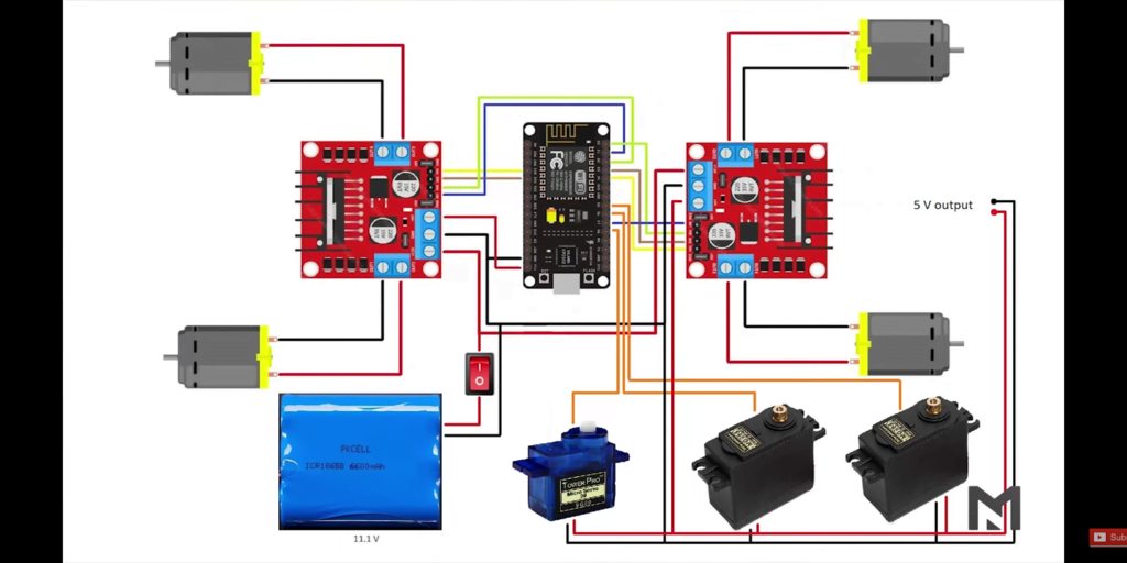
As a final step, attach the front and back panels using M3 screws of 15mm length. Since it’s an all-terrain robot, you can attach an FPV camera on top of it to view the real-time footage. A 5V output can be used to power the camera.
Testing Of The Claw Arm
Switch it ON from the bottom and connect it via a WI-FI hotspot. Type in the IP address that has been generated from the code(Discussed in DIY Arduino Car Blog For Details: Click Here).
Perform operations like, moving forward and backward or picking loads. When observed, its safe limit to lift any object was 500gms. Any weight above that vibrates the mechanical arm. It works smoothly on rough surfaces and can be used for off-roading.
You can also watch our youtube video for better understanding.
FAQ Related To Claw Arm Arduino Car
Yes, it can work off-road but the movements will be limited to moving forward-backward and left-right turns. It won’t be able to perform sideway movements which are iconic for Mecanum Wheels.
If you want simple movement controls then you can download them from here. If you want to customize it then you can use Arduino IDE. The open-source Arduino IDE runs on Windows, Mac OS X, and Linux. Download the Arduino software (depending on your OS) from the official website and follow the instructions to install it.
A very common restriction is the limitation of processing in one Arduino board in the case of multiple peripherals.
Conclusion
There are many things you can do with your claw arm kit and one of them is to create different manners to control the robotic arm. You can create a robotic arm using several ARDUINO APIs.
If you have any questions about how to select the connections or mounting of the claw, feel free to use the comment box. Looking forward to your feedback.
THANK YOU!